
Profiles and applications
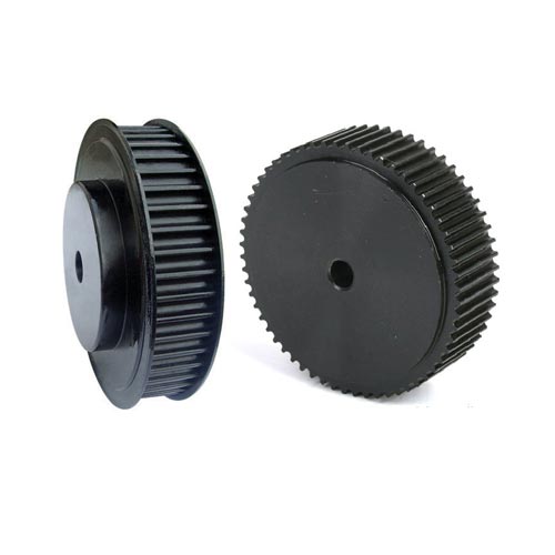
What are timing pulleys for synchronous belts?
A timing pulley is a toothed wheel designed to work with a synchronous (toothed) belt. Unlike V-belt drives, a synchronous drive provides precise motion transmission without slippage — the teeth of the pulley mesh mechanically with the teeth of the belt, guaranteeing a constant transmission ratio at all times.
Nibora Ltd. offers timing pulleys to ISO 5294 standard with pilot bore (centre bore), in profiles MXL, XL, L, H, XH, HTD, T and BAT. Materials: aluminium alloy UNI 9006-T6 (light series MXL, XL) and steel / grey cast iron (series L, H, XH). Tooth count: 10 to 120.
What drives are timing pulleys used for?
Synchronous belt drives are the essential choice wherever precise motion synchronisation is required — no slip, no step loss. The key advantage over V-belt drives: zero slip, compact design, quiet operation, no lubrication required.
| Industry / Application | Specific use |
|---|---|
| CNC machines and robotics | Axis drives, positioning, linear actuators |
| Printers and plotters | Precise printhead positioning |
| Medical equipment | Dosing pumps, X-ray machines, laboratory devices |
| Packaging industry | Conveyor belt synchronisation, dosing |
| Food processing | Synchronisation of feeding mechanisms |
| Textile industry | Weaving and spinning machines — precise pitch |
| Automation / SCARA robots | Joint drives with precise positioning |
| Agricultural machinery | Combines — knife bar synchronisation |
| General engineering | Any drive requiring synchronous transmission without slip |
Catalogue data
Profiles — comparison table
| Profile | Pitch | Belt widths (F) | Teeth | Material | System |
|---|---|---|---|---|---|
| MXL | 2.032 mm (0.080″) | 6.4 mm (025) | 16–72 | Aluminium UNI 9006-T6 | Imperial |
| XL | 5.080 mm (3/16″) | 9.5 mm (037) | 10–72 | Aluminium UNI 9006-T6 | Imperial |
| L | 9.525 mm (3/8″) | 12.7–25.4 mm (050–100) | 10–96 | Steel / Cast iron | Imperial |
| H | 12.700 mm (1/2″) | 19.1–76.2 mm (075–300) | 14–120 | Steel / Cast iron | Imperial |
| XH | 22.225 mm (7/8″) | 50.8–101.6 mm (200–400) | 18–34 | Steel | Imperial |
| HTD 3M/5M/8M/14M | 3/5/8/14 mm | On request | On request | Steel / Al | Metric HTD |
| T 2.5/5/10 | 2.5/5/10 mm | On request | On request | Steel / Al | Metric T |
| BAT 5/10 | 5/10 mm | On request | On request | Steel / Al | Metric BAT |
Note: for HTD, T and BAT series the catalogue data is a flange-code cross-reference. Full technical parameters on request from Nibora Ltd.
Mounting types (flanges)
| Code | Description | Application |
|---|---|---|
| 1F | 1 flange — single side | Small MXL pulleys, light drives |
| 2F | 2 flanges — both sides (standard) | Standard mounting for most applications |
| 4 | No flange — body only | Cast iron, higher tooth counts, multi-belt systems |
| 4F | 4 flanges / cast iron | Heavy drives, wide belts |
Catalogue data — series MXL 025 (Aluminium)
Pitch 2.032 mm · Width F = 8.5 mm · Depth L = 16 mm · Standard bore: pilot (centre)
| Code | Type | Teeth | dp (mm) | de (mm) | Df (mm) | Dm (mm) | Kg |
|---|---|---|---|---|---|---|---|
| 16 MXL 025 | 1F | 16 | 10.35 | 9.84 | 15 | 15 | 0.01 |
| 18 MXL 025 | 1F | 18 | 11.64 | 11.13 | 16 | 16 | 0.01 |
| 20 MXL 025 | 1F | 20 | 12.94 | 12.43 | 16 | 16 | 0.01 |
| 22 MXL 025 | 2F | 22 | 14.23 | 13.72 | 18 | 10 | 0.01 |
| 24 MXL 025 | 2F | 24 | 15.52 | 15.02 | 18 | 10 | 0.01 |
| 28 MXL 025 | 2F | 28 | 18.11 | 17.60 | 23 | 11 | 0.01 |
| 30 MXL 025 | 2F | 30 | 19.40 | 18.90 | 23 | 12 | 0.02 |
| 32 MXL 025 | 2F | 32 | 20.70 | 20.19 | 25 | 14 | 0.02 |
| 36 MXL 025 | 2F | 36 | 23.29 | 22.78 | 28 | 16 | 0.02 |
| 40 MXL 025 | 2F | 40 | 25.87 | 25.36 | 32 | 18 | 0.03 |
| 44 MXL 025 | 2F | 44 | 28.46 | 27.95 | 36 | 18 | 0.03 |
| 48 MXL 025 | 2 | 48 | 31.05 | 30.54 | — | 20 | 0.03 |
| 60 MXL 025 | 2 | 60 | 38.81 | 38.30 | — | 24 | 0.04 |
| 72 MXL 025 | 2 | 72 | 46.57 | 46.06 | — | 25 | 0.05 |
Catalogue data — series XL 037 (Aluminium)
Pitch 5.080 mm · Width F = 14.3 mm · Standard bore: pilot
| Code | Type | Teeth | dp (mm) | de (mm) | Df (mm) | d (mm) | Kg |
|---|---|---|---|---|---|---|---|
| 10 XL 037 | 2F | 10 | 16.17 | 15.66 | 23 | — | 0.01 |
| 12 XL 037 | 2F | 12 | 19.40 | 18.90 | 25 | — | 0.01 |
| 14 XL 037 | 2F | 14 | 22.64 | 22.13 | 28 | — | 0.02 |
| 16 XL 037 | 2F | 16 | 25.87 | 25.36 | 32 | — | 0.03 |
| 18 XL 037 | 2F | 18 | 29.11 | 28.60 | 36 | — | 0.04 |
| 20 XL 037 | 2F | 20 | 32.34 | 31.83 | 38 | — | 0.05 |
| 22 XL 037 | 2F | 22 | 35.57 | 35.07 | 42 | — | 0.06 |
| 24 XL 037 | 2F | 24 | 38.81 | 38.30 | 44 | — | 0.06 |
| 26 XL 037 | 2F | 26 | 42.04 | 41.53 | 48 | 8 | 0.09 |
| 28 XL 037 | 2F | 28 | 45.28 | 44.77 | 51 | 8 | 0.10 |
| 30 XL 037 | 2F | 30 | 48.51 | 48.00 | 54 | 8 | 0.12 |
| 36 XL 037 | 2 | 36 | 58.21 | 57.70 | — | 8 | 0.14 |
| 40 XL 037 | 2 | 40 | 64.68 | 64.17 | — | 8 | 0.16 |
| 48 XL 037 | 2 | 48 | 77.62 | 77.11 | — | 10 | 0.19 |
| 60 XL 037 | 2 | 60 | 97.02 | 96.51 | — | 10 | 0.22 |
| 72 XL 037 | 2 | 72 | 116.42 | 115.92 | — | 10 | 0.44 |
Catalogue data — series L (Steel / Cast iron, excerpt)
Pitch 9.525 mm · Widths: L 050 (F=19.0 mm), L 075 (F=25.4 mm), L 100 (F=31.8 mm) · Steel: 10–48 teeth · Cast iron: 50–96 teeth
| Code | Material | Teeth | dp (mm) | de (mm) | Df (mm) | d (mm) | Kg |
|---|---|---|---|---|---|---|---|
| 10 L 050 | St | 10 | 30.32 | 29.56 | 36 | 8 | 0.11 |
| 14 L 050 | St | 14 | 42.44 | 41.68 | 48 | 8 | 0.24 |
| 18 L 050 | St | 18 | 54.57 | 53.81 | 60 | 10 | 0.44 |
| 24 L 050 | St | 24 | 72.77 | 72.00 | 79 | 10 | 0.81 |
| 30 L 050 | St | 30 | 90.96 | 90.20 | 97 | 12 | 1.17 |
| 36 L 050 | St | 36 | 109.15 | 108.39 | 115 | 12 | 1.70 |
| 48 L 050 | St | 48 | 145.53 | 144.77 | 152 | 12 | 2.78 |
| 60 L 050 | GG | 60 | 181.91 | 181.15 | — | 14 | 2.41 |
| 72 L 050 | GG | 72 | 218.29 | 217.53 | — | 14 | 2.82 |
| 96 L 050 | GG | 96 | 291.06 | 290.30 | — | 14 | 3.42 |
Catalogue data — series H (Steel / Cast iron, excerpt)
Pitch 12.700 mm (1/2″) · Widths: H 075–H 300 · Steel: 14–40 teeth · Cast iron: 44–120 teeth
| Code | Belt width F | Teeth | dp (mm) | de (mm) | Bore d (mm) | Kg |
|---|---|---|---|---|---|---|
| 14 H 075 | 26.4 mm | 14 | 56.59 | 55.22 | 10 | 0.58 |
| 20 H 075 | 26.4 mm | 20 | 80.85 | 79.48 | 12 | 1.27 |
| 30 H 075 | 26.4 mm | 30 | 121.29 | 119.90 | 14 | 2.76 |
| 40 H 075 | 26.4 mm | 40 | 161.70 | 160.33 | 14 | 4.58 |
| 14 H 100 | 31.8 mm | 14 | 56.59 | 55.22 | 12 | 0.65 |
| 20 H 100 | 31.8 mm | 20 | 80.85 | 79.48 | 14 | 1.44 |
| 30 H 100 | 31.8 mm | 30 | 121.29 | 119.90 | 14 | 3.19 |
| 60 H 100 | 31.8 mm | 60 | 242.55 | 241.18 | 18 | 5.30 |
| 96 H 100 | 31.8 mm | 96 | 388.08 | 386.71 | 18 | 10.25 |
| 120 H 100 | 31.8 mm | 120 | 485.10 | 483.73 | 18 | 13.09 |
| 14 H 200 | 58.7 mm | 14 | 56.59 | 55.22 | 18 | 1.10 |
| 30 H 200 | 58.7 mm | 30 | 121.29 | 119.90 | 18 | 5.47 |
| 60 H 200 | 58.7 mm | 60 | 242.55 | 241.18 | 24 | 8.25 |
| 120 H 200 | 58.7 mm | 120 | 485.10 | 483.73 | 28 | 19.15 |
| 14 H 300 | 85.7 mm | 14 | 56.59 | 55.22 | 18 | 1.64 |
| 30 H 300 | 85.7 mm | 30 | 121.29 | 119.90 | 18 | 7.90 |
| 60 H 300 | 85.7 mm | 60 | 242.55 | 241.18 | 24 | 11.18 |
Catalogue data — series XH (Steel)
Pitch 22.225 mm (7/8″) · Widths: XH 200 (65 mm), XH 300 (92 mm), XH 400 (119 mm) · Steel only, type 2F
| Code | Belt width F | Teeth | dp (mm) | de (mm) | Bore d (mm) | Kg |
|---|---|---|---|---|---|---|
| 18 XH 200 | 65 mm | 18 | 127.34 | 124.55 | 24 | 6.00 |
| 24 XH 200 | 65 mm | 24 | 169.79 | 166.99 | 24 | 11.47 |
| 30 XH 200 | 65 mm | 30 | 212.23 | 209.44 | 24 | 17.69 |
| 34 XH 200 | 65 mm | 34 | 240.53 | 237.74 | 24 | 22.75 |
| 18 XH 300 | 92 mm | 18 | 127.34 | 124.55 | 28 | 8.90 |
| 28 XH 300 | 92 mm | 28 | 198.09 | 195.29 | 28 | 22.27 |
| 34 XH 300 | 92 mm | 34 | 240.53 | 237.74 | 28 | 34.20 |
| 18 XH 400 | 119 mm | 18 | 127.34 | 124.55 | 32 | 9.60 |
| 28 XH 400 | 119 mm | 28 | 198.09 | 195.29 | 32 | 27.23 |
| 34 XH 400 | 119 mm | 34 | 240.53 | 237.74 | 32 | 40.00 |
Pitch diameter formula
dp = (z × p) / π, where z = number of teeth, p = pitch in mm. Example: 30 teeth, H profile (p = 12.7 mm) → dp = (30 × 12.7) / π = 121.29 mm (per catalogue). Transmission ratio i = z2/z1 is calculated from tooth counts, because there is no slip.
Timing pulleys ISO 5294
Download PDF ↓Frequently Asked Questions
What is the difference between a timing pulley and a V-belt pulley?
A timing pulley works with a toothed (synchronous) belt — the teeth mesh mechanically, providing zero slip. A V-belt pulley works by friction with a trapezoidal belt — slip is possible under overload. Synchronous drives are mandatory for precise positioning, CNC, robotics and motion synchronisation.
What does 'pitch' mean for timing pulleys?
Pitch is the distance between the centres of two adjacent teeth, measured along the pitch circle. MXL: 2.032 mm; XL: 5.08 mm; L: 9.525 mm; H: 12.7 mm; XH: 22.225 mm. Metric profiles: HTD 3M=3 mm, 5M=5 mm, 8M=8 mm, T5=5 mm, T10=10 mm. The pulley and belt MUST have the same pitch.
How is the pitch diameter calculated?
dp = (z × p) / π, where z is the tooth count and p is the pitch in mm. Example: 24 teeth, XL profile (p=5.08 mm) → dp = (24 × 5.08) / π = 38.81 mm. Transmission ratio: i = z2/z1 — calculated from tooth counts, not diameters, because there is no slip.
What is the difference between Imperial (MXL/XL/L/H/XH) and metric (HTD/T/BAT) profiles?
Imperial profiles have inch-based pitch and a trapezoidal tooth form. HTD profiles have a rounded (parabolic) tooth form — lower belt bending stress, higher power capacity for the same size. T and BAT profiles are metric standards for more precise drives. When replacing, always match both profile type and pitch.
What is the difference between types 1F, 2F, 4 and 4F?
The type defines the flange configuration. 1F — single flange (one side). 2F — double flange (both sides) — standard for most applications. 4 — no flange (body only). 4F — four flanges / heavy-duty cast iron execution. Flanges prevent lateral belt slipping off the pulley.
Can timing pulleys be supplied with a specific bore diameter?
Pulleys are supplied with a pilot (centre) bore and are subsequently bored to the required shaft diameter. Nibora Ltd. can supply pulleys ready-bored or bore them to your specification. When ordering, state: profile, tooth count, belt width, shaft diameter.
How do I choose the right profile for my application?
MXL/XL — low power, precision drives, robotics, printers. L — medium power, conveyors, packaging machines. H — heavier drives, industrial machinery. XH — heavy drives with large pitch. HTD — when higher power is needed in a compact size (metric system). For selection assistance, contact nibora@nibora.com.